
 EN
EN
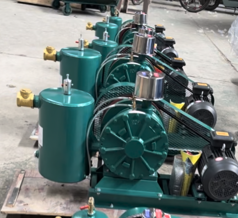
A rotary lobe blower is a critical component in modern air compression systems, operating on positive displacement principles to deliver consistent, high-volume airflow at relatively low pressure. Unlike centrifugal compressors that accelerate air using spinning impellers, a rotary lobe blower moves air through fixed increments by trapping pockets of gas between rotating lobes and the housing wall, then forcing that air into the discharge line. This fundamental design enables the device to maintain steady output regardless of downstream pressure changes, making it ideal for applications requiring reliable, non-pulsating air delivery.
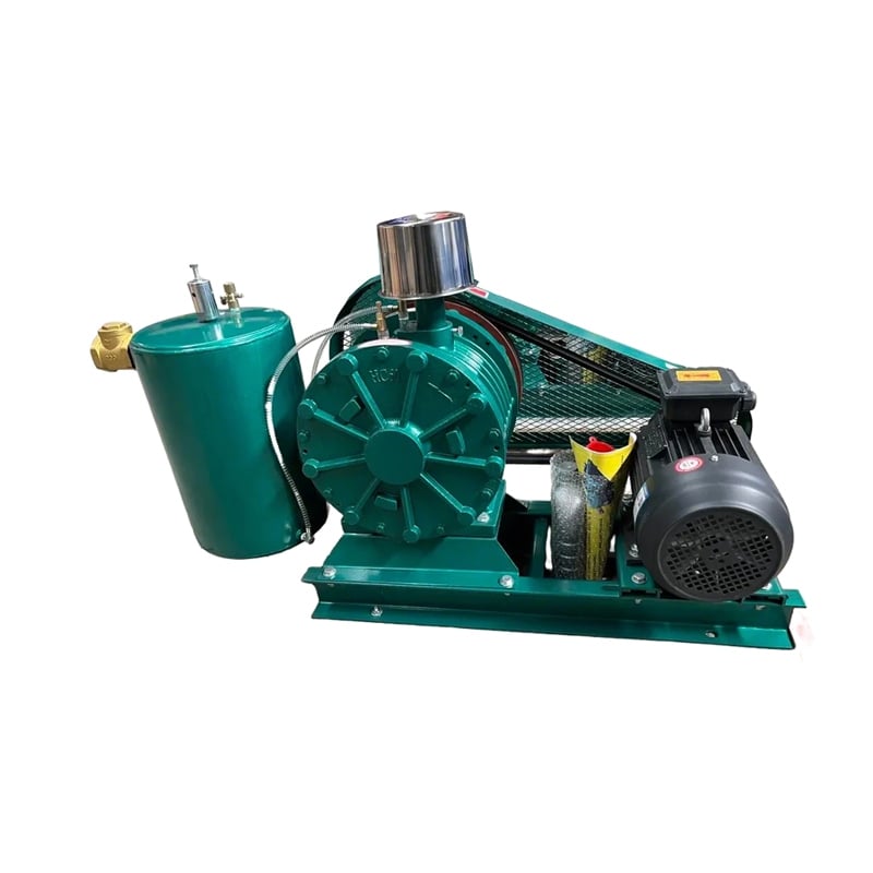
The operational efficiency of a rotary lobe blower stems from its capacity to deliver low pressure high volume air pump specifications while maintaining mechanical simplicity and durability. The two rotating lobes, typically shaped like figure-eights or twisted hourglasses, rotate in opposite directions at precisely synchronized speeds through timing gears. As each lobe rotates, it traces a path that creates expanding cavities on the inlet side and shrinking cavities on the discharge side, creating a continuous pumping action without requiring internal compression stages.
Core Operating Principle and Mechanical Design
Positive Displacement Mechanism
The positive displacement blower applications depend fundamentally on the mechanical trapping and moving of fixed air volumes. When the inlet port aligns with the expanding cavity, atmospheric air or pre-pressurized gas enters the chamber. As rotation continues, the inlet port closes and the trapped air volume decreases as the lobes push it toward the discharge port. This controlled, volumetric movement guarantees that the same quantity of air exits with each complete rotation cycle, regardless of outlet pressure variation. The design eliminates the need for internal valve systems, reducing maintenance complexity compared to reciprocating compressors.
Rotor Configuration and Timing
Two precisely manufactured rotors must maintain exact timing and clearance tolerances to function effectively. The timing gears synchronize rotation speed and prevent the lobes from contacting each other or the housing, which would cause catastrophic mechanical failure. Typical rotary blower maintenance and troubleshooting protocols focus on ensuring gear alignment and lobe clearance remain within specification. Most industrial rotary lobe blowers operate at speeds between 500 and 3,600 revolutions per minute, with higher speeds generating greater airflow volume. The distance between rotor surfaces and the housing is typically maintained at 0.004 to 0.010 inches, requiring precision manufacturing and regular inspection to prevent performance degradation or binding.
Performance Characteristics and Application Scope
Airflow Volume and Pressure Output
A rotary lobe blower excels at moving large air volumes at relatively modest pressure levels, typically ranging from 5 to 15 pounds per square inch gauge in most industrial configurations. This characteristic defines the low pressure high volume air pump specifications that make these devices suitable for wastewater aeration, pneumatic conveying, and vacuum services. The volumetric displacement remains constant across the operating range, meaning a rotary lobe blower rated for 500 cubic feet per minute will deliver approximately that volume regardless of whether the discharge pressure is 5 or 12 pounds per square inch. This predictability makes capacity planning straightforward for engineers designing air handling systems.
Real-World Operational Benefits
Industries depend on positive displacement blower applications because they deliver uninterrupted, pulsation-free airflow essential for sensitive processes. Wastewater treatment facilities use rotary lobe blowers for aeration basins where steady oxygen transfer directly impacts biological treatment efficiency. Food processing operations employ these blowers for pneumatic ingredient transport without product damage that pulsating air might cause. The consistent delivery also reduces downstream noise and vibration compared to reciprocating or turbo-compressor alternatives. Temperature rise in the discharged air remains moderate due to the low-pressure, high-volume nature of the operation.
Maintenance Requirements and Troubleshooting Protocols
Preventive Maintenance Essentials
Effective rotary blower maintenance and troubleshooting begins with establishing regular inspection schedules and maintaining accurate maintenance logs. Oil analysis should occur every 500 operating hours, monitoring viscosity, particle count, and water content to catch developing issues before catastrophic failure occurs. Rotor timing should be verified annually using precision dial indicators to confirm that clearances have not drifted outside acceptable ranges. Bearing condition assessment through vibration analysis or infrared temperature monitoring can identify wear patterns early, allowing scheduled replacement before unexpected downtime disrupts operations. Maintaining system cleanliness through inlet air filtration prevents particulate accumulation that would increase rotor friction and reduce efficiency.
Common Failure Modes and Resolution Strategies
The most frequent rotary lobe blower failure involves timing gear wear, causing rotor-to-housing contact and subsequent mechanical damage. Symptoms include increased operational noise, temperature rise above normal operating range, and reduced discharge pressure at a given speed. Displacement of the inlet filter media into the blower housing can restrict airflow and create localized pressure spikes that stress internal components. Seal deterioration allows oil loss and external air leakage, reducing system efficiency and requiring immediate seal replacement. Understanding these failure modes enables operators to implement corrective action quickly, minimizing emergency shutdowns and production interruptions. Documentation of failure history helps identify systemic issues requiring design modifications or operational procedure adjustments.
Integration into Broader Air Compression Systems
System Design Considerations
When integrating a rotary lobe blower into facility air systems, engineers must account for discharge temperature, inlet filtration requirements, and downstream equipment compatibility. Low pressure high volume air pump specifications demand proper piping sizing to prevent excessive velocity losses that would require increased motor horsepower to achieve target outlet pressures. Sound attenuation becomes important in occupied areas, with many installations requiring discharge silencers or acoustic enclosures. Motor selection must match the volumetric displacement and target operating speed, accounting for service factor requirements and potential future capacity expansion. Inlet air conditions including temperature, humidity, and contamination levels directly influence blower performance and bearing life.
Performance Optimization and Efficiency Gains
Optimizing rotary lobe blower efficiency involves matching the unit size precisely to system demand rather than oversizing for future expansion. Variable frequency drives can reduce energy consumption during partial-load operation by allowing speed adjustment proportional to actual airflow requirements. Thermal management through proper cooling maintains viscosity of the lubricant, reducing internal friction losses. Regular inlet filter changes prevent backpressure buildup that would force the motor to work harder for the same discharge volume. Monitoring differential pressure across the inlet filter guides timely replacement, preventing the gradual performance degradation that occurs when filter media becomes saturated with accumulated dust.
FAQ
What distinguishes a rotary lobe blower from other compression technologies?
A rotary lobe blower uses positive displacement to move fixed air volumes per rotation cycle, delivering consistent output independent of discharge pressure. This differs fundamentally from centrifugal compressors that accelerate air using impeller speed, where output changes with resistance. The rotary design offers lower operating temperatures, simpler maintenance, and superior reliability for continuous-duty applications where steady airflow matters more than high pressure.
How does positive displacement blower applications impact system design?
Positive displacement blower applications eliminate pressure variability since output remains constant regardless of downstream resistance. This enables precise capacity planning and allows engineers to specify smaller motor horsepower compared to devices that require oversizing to handle pressure spikes. The predictable output also simplifies control strategies, often requiring simple on-off or variable-frequency-drive speed control rather than complex pressure-compensating systems.
What are the primary rotary blower maintenance and troubleshooting steps for facility operators?
Rotary blower maintenance and troubleshooting requires monthly visual inspections for oil level and leaks, quarterly oil analysis for contamination monitoring, and semi-annual vibration checks to identify bearing wear. Inlet filter changes based on differential pressure readings prevent performance loss. Annual timing gear verification and bearing lubrication according to manufacturer specifications ensure long operational life. Documentation of any noise changes, temperature increases, or pressure variations guides diagnostic decisions.